 Plonkish Gadgets
Essential gadgets for building Plonkish constraint circuits
Writing Arithmetic Circuits
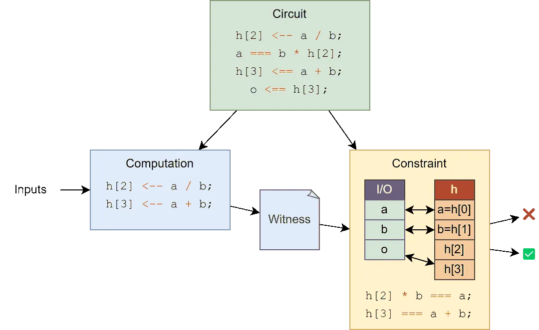
💡 Circuit Structure: Original circuit code consists of two key parts:
- 💻 Computation: Determines how values are calculated during proof generation
- 🔒 Constraints: Verifies the correctness of those calculations
While we typically write these together in our code, the compiler separates them. The constraints are fixed during the setup phase and become the core verification logic, while the computation part runs with private and public inputs during each proof generation.
Plonkish Arithmetic Circuits
Plonkish arithmetic circuits are different from R1CS-like circuits in that they are designed to resemble a table, rather than a simple list of computations. This design makes the circuit more complex to reason about, but also provides some advantages in terms of computational efficiency.
-
📊 Table Design
- A column is a polynomial
- A row is a root of unity
- A cell is the evaluation of a polynomial at a root of unity
-
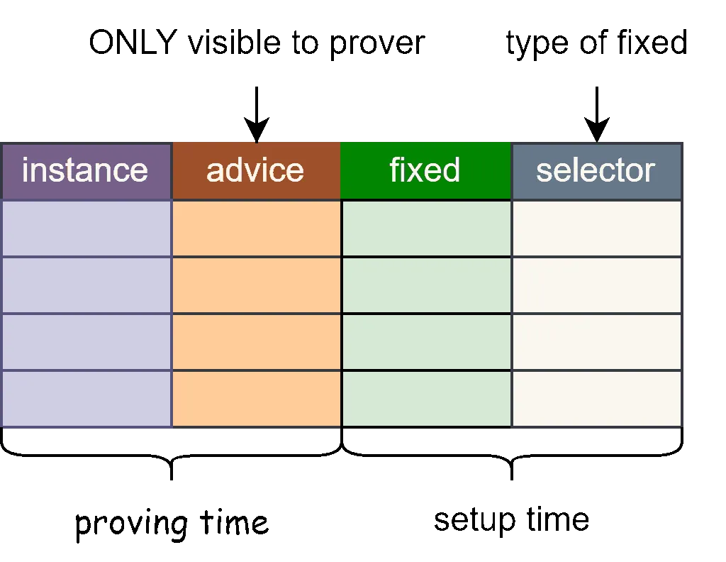
📋 Column Types
- 🔒 Advice: Advice columns, private inputs and intermediate data, all private data
- 📌 Fixed: Constant columns, fixed values when creating the circuit, public data
- 🔘 Selector: Selector columns, virtual columns, essentially constant columns, binary used to switch custom gate circuits
- 📢 Instance: Instance columns, store public inputs (and public outputs)
-
🔄 Arithmetic Circuit
- ✨ Custom gates
- 🔍 Lookup table
- 🔗 Copy constraints
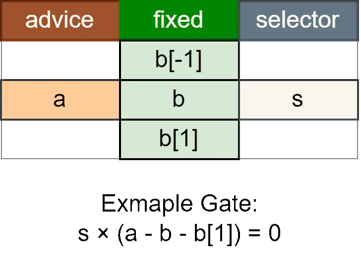
Custom Gates
- ✨ Custom gates are expressions that constrain multiple cells
- 🔘 Selectors are essentially fixed constant columns. They are boolean, used to enable or disable gates
- 🔄 We can reference cells from the previous row, next row, but max to 7 in halo2.
- 📝 In our examples, we use
b[1]to represent the next row
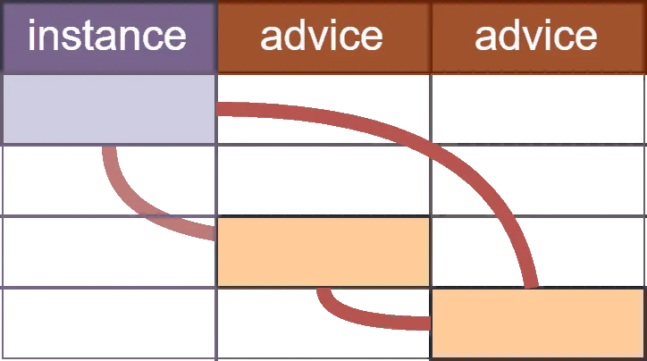
Copy Constraints
- 🔗 Copy constraints bind two cells together, ensuring their values must be the same
- ⚡ These are the most efficient constraints. We can use them as much as we want
Lookup Tables
Lookup tables are very efficient for range checks and bit operations
⚡ XOR Example:
Instead of using complex constraints to implement XOR, we can use a lookup table:
| a | b | a ⊕ b |
|---|---|---|
| 0 | 0 | 0 |
| 0 | 1 | 1 |
| 1 | 0 | 1 |
| 1 | 1 | 0 |
Using a lookup gate, we can verify that for any inputs (a, b) and output c, the triplet (a, b, c) appears in our XOR truth table, making bit operations much more efficient than implementing them with arithmetic constraints.
Gate Tricks
🎨 Writing circuits in Plonkish is totally different from writing circuits in R1CS (Circom) or zkVM program.
Here are some tricks that might help you write circuits in Plonkish.
Limiting Values
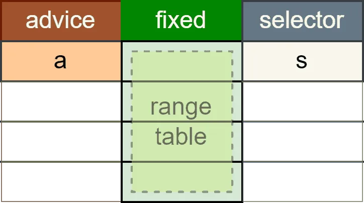
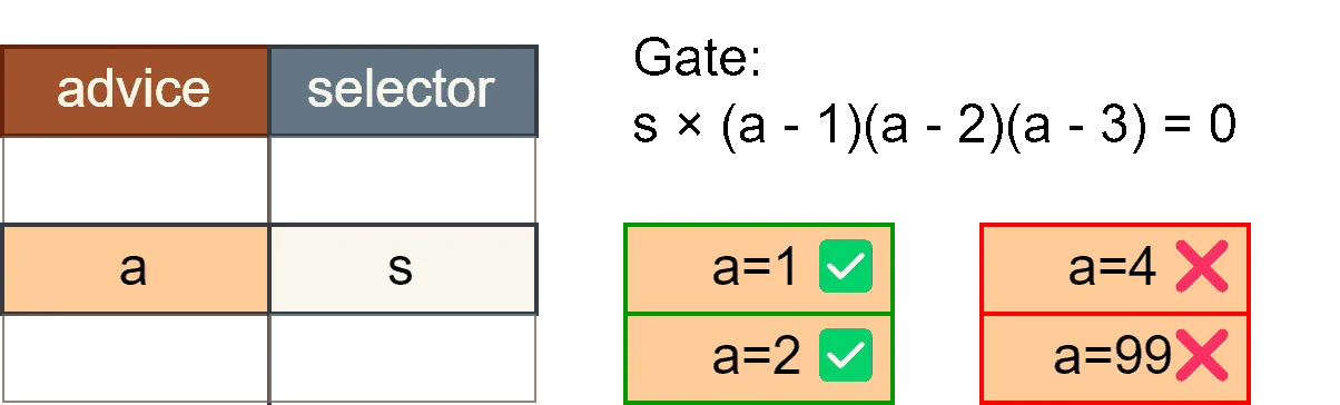
Sometimes we need to limit a value to a specific set of values. For example, we might want to ensure that a value is either 1, 2, or 3.
🔢 Limiting Value Gate:
- This gate enforces that can only take one of the values 1, 2, or 3 when .
- If , the first term becomes 0, making the entire expression 0.
- If , the second term becomes 0, making the entire expression 0.
- If or , none of the terms become 0, so the expression will not be 0.
- Similarly, if is any other value, the gate will not satisfy the equation unless , which means the selector is disabled.
If-Else Condition
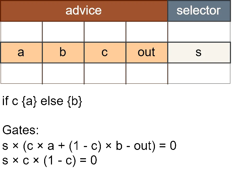
Implementing conditional logic in ZK circuits requires special techniques. Here’s how to implement an if-else condition:
🔀 Conditional Output Gate:
- This gate enforces that the output is either or depending on the value of .
- If , the output will be .
- If , the output will be .
🔍 Selector Validity Gate (Boolean Gate):
- This gate ensures that is a valid boolean value (either 0 or 1).
Together, these gates implement the conditional logic .
Is-Zero Check
Checking if a value is zero is a common operation in ZK circuits, but it requires special handling:
🔍 Is-Zero Definition:
The value is defined as:
The output is calculated as:
With the constraint:
This technique allows us to check if a value is zero and produce a boolean result (1 for zero, 0 for non-zero).
| Case | input | inv | output | input × output |
|---|---|---|---|---|
| Non-zero input | 4 | 1/4 | 0 | 0 |
| Zero input | 0 | 0 | 1 | 0 |
| Non-zero input (malicious inv) | 4 | 1/5 | 1/5 | 4/5 |
| Zero input (malicious inv) | 0 | 1/5 | 1 | 0 |
If-Equal Condition
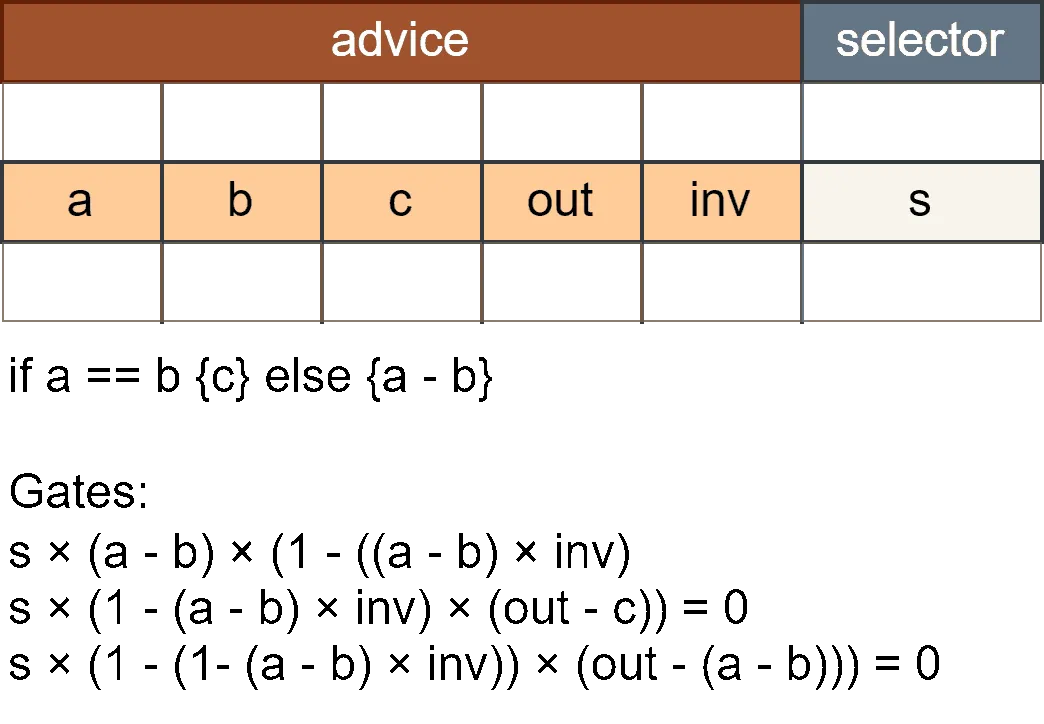
The if-equal condition implements: out = a == b ? c : (a - b). This technique combined the tricks from is-zero and if-else.
🔀 Gate 1: Equality Check (via is-zero)
- This gate ensures that if , the expression becomes 0.
- From
is-zero, we know that and is the inverse of . - When , the gate enforces the calculation based on and its inverse.
🔀 Gate 2: Output Assignment
- This gate enforces that when , the output must equal .
- If , this constraint is automatically satisfied.
🔀 Gate 3: Alternative Output
- This gate enforces that when , the output is set to .
- If , this constraint is automatically satisfied.
💡 Together, these three gates implement the conditional structure:
- When : The output is set to .
- When : The output is set to .

More tricks to come
More circuit tricks and techniques will be added soon.